Solved Click to see additional instructionsOp Amp LowPass Circuit Diagram
Solved Click to see additional instructionsOp Amp LowPass Circuit Diagram Step-by-step design of Active low pass filter using Op Amplifier. So as you can see, there a number of factors that go into creating a low pass filter with an op amp. If you are dealing with high-frequency signals, then it's best to use a much higher-speed op amp than the LM741. For relatively low frequencies, it should suffice. And this is how a low pass filter circuit can be an op amp. Related Resources
Hi, thanks for watching our video about active filters! In this video we'll walk you through:- How to design, simulate and build active opamp filters- Using
How to Build an Active Low Pass Filter Circuit with an Op Amp Circuit Diagram
Active Low-Pass Filter Design Jim Karki AAP Precision Analog ABSTRACT This report focuses on active low-pass filter design using operational amplifiers. Low-pass filters are commonly used to implement anti-aliasing filters in data acquisition systems. Design of second-order filters is the main topic of consideration.

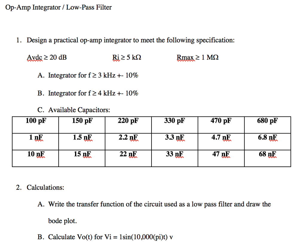
1. To design a First Order Low Pass OR a High Pass Filter using an Op-Amp and a designated capacitor as the frequency determining component. 2. Build the low-pass or high-pass filter of your design and check its frequency response. Drive the circuit with a sine wave and record input (constant) and output voltage for different frequencies.

PDF Active Low Circuit Diagram
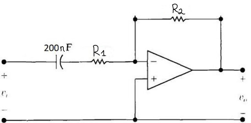
This type of filter is also known as a single-pole RC filter, since it involves only one reactive component. The typical configuration of a first-order low-pass filter with an operational amplifier is called a low-pass RC filter. In RC low pass filter, the capacitor is connected between the inverting input of the op amp and its output. The low pass and high pass filter can be combined into a band pass filter. In the examples below the corner frequencies were chosen to be the audio band (20Hz - 20KHz). Notice the difference in the gain outside of the pass band. The gain of the inverting amplifier continues to drop as you get farther away from the pass band.