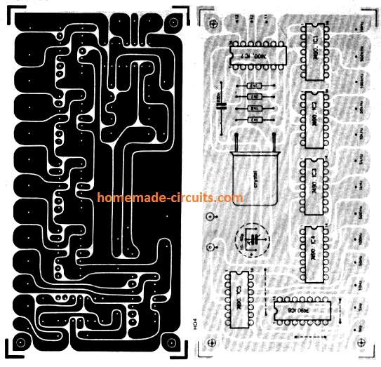
SIMPLEFREQUENCYGENERATOR Circuit Diagram
SIMPLEFREQUENCYGENERATOR Circuit Diagram The bridge circuit is C1 R4a and C3 R4b. R4 is a dual-ganged potentiometer and controls the frequency, which is 1/2πRC. Assuming R4 is central, say 2k, this would be 1/(2*π* 5k * 0.01u) = 3kHz. The lamp is a small 12V incandescent light bulb.As the filament heats up, its resistance goes up, reducing the current through it, reducing the gain and amplitude at the output, so you have a very
In the video, I will show you how to DIY a simple frequency generator or oscillator by using IC NE555 and a few common parts. Step by step in details. In today's video we learn how to make a frequency / tone generator out of simple parts that can be easily obtained, this is a great project for a starter to WHAT IS THISLearn how to make a DIY frequency generator circuit using only a couple of components. RESOURCES Frequency Generator Schematic - https://drive

10 Useful Function Generator Circuit Diagrams Explained
In my last instructable i showed you how to build pwm signal generator, and i used it to filter some other waveforms from it. In this instructable i will show you how to make simple function/frequency generator, how to drive relay with it and how blink led without arduino. All you need is: 10uF cap ; 1uF cap ; 100nF cap ; 2 x 10nF cap ; 100 pF

1) Using IC 4049. Using only one low-cost CMOS IC 4049 and a handful of separate modules, it is easy to create a robust function generator that will provide a range of three waveforms around and beyond the audio spectrum.. The purpose of the article was to create a basic, cost-effective, open source frequency generator that is easy to construct and used by all hobbyists and lab professionals.

How to make a Tone Generator Circuit Diagram
This is a simple function generator that works in the audio frequency range. It can be useful for amplifier testing, experimentation in DSP. LOGIN Author's prototype for Arduino based frequency generator. Circuit diagram of the sine, square and ramp Arduino-based frequency generator is shown in Fig. 2. It is built around an Ardunio Uno The 9 simple sine wave generator circuits presented in the following article are easy to build, since they incorporate a small number of ordinary electronic. It is possible to make the output frequency of the sine wave adjustable by replacing the R1 and R2 with fixed resistors and by putting a potentiometer in series, and it is certainly