Quality Gas Monitor With Notifications On Phone Email Circuit Diagram
Quality Gas Monitor With Notifications On Phone Email Circuit Diagram Overview. In this project, we will learn how to make our own IoT Based Electricity Energy Meter using ESP32 & monitor data on the Blynk Application.Earlier we built IoT DC Energy Meter and GSM Prepaid Energy Meter.With the current technology, you need to go to the meter reading room and take down readings. Thus monitoring and keeping track records of your electricity consumption is a tedious task. Here we build a Smart real time energy monitoring device to determine the exact and instantaneous consumption of but they come with a heavy price tag and also with devoid you of the learning and fun experience of DIY. Components Required to build Smart Power Consumption Meter. ESP32 WROOM 32D Module; HI LINK 5V 3W SMPS; 0.96" 128X64
First you need to start by assembling the components onto the CT or onto your breadboard in order to create your current sensor which produces a signal which your Arduino can understand. An Arduino only has analogue voltage inputs which measure 0-5V DC, so you need to convert the current output from the CT into a voltage reference and then Overview: IoT Energy Meter using ESP8266 & INA219. Today we will make an IoT based energy meter using the INA219 sensor and ESP8266, NodeMCU, OLED Display, and Blink IoT Cloud. This small device can be very useful for you in your day-to-day life.
Simple Arduino Home Energy Meter : 5 Steps (with Pictures ... Circuit Diagram
In this cabinet I mounted the energy meter on the wall using a wall plug; in order to screw the energy meter to the wall, I drilled a hole in the back of the 3D printed box. Lastly I connected the current clamp cable to the energy meter module, closed the lid and finally plugged in the energy meter.
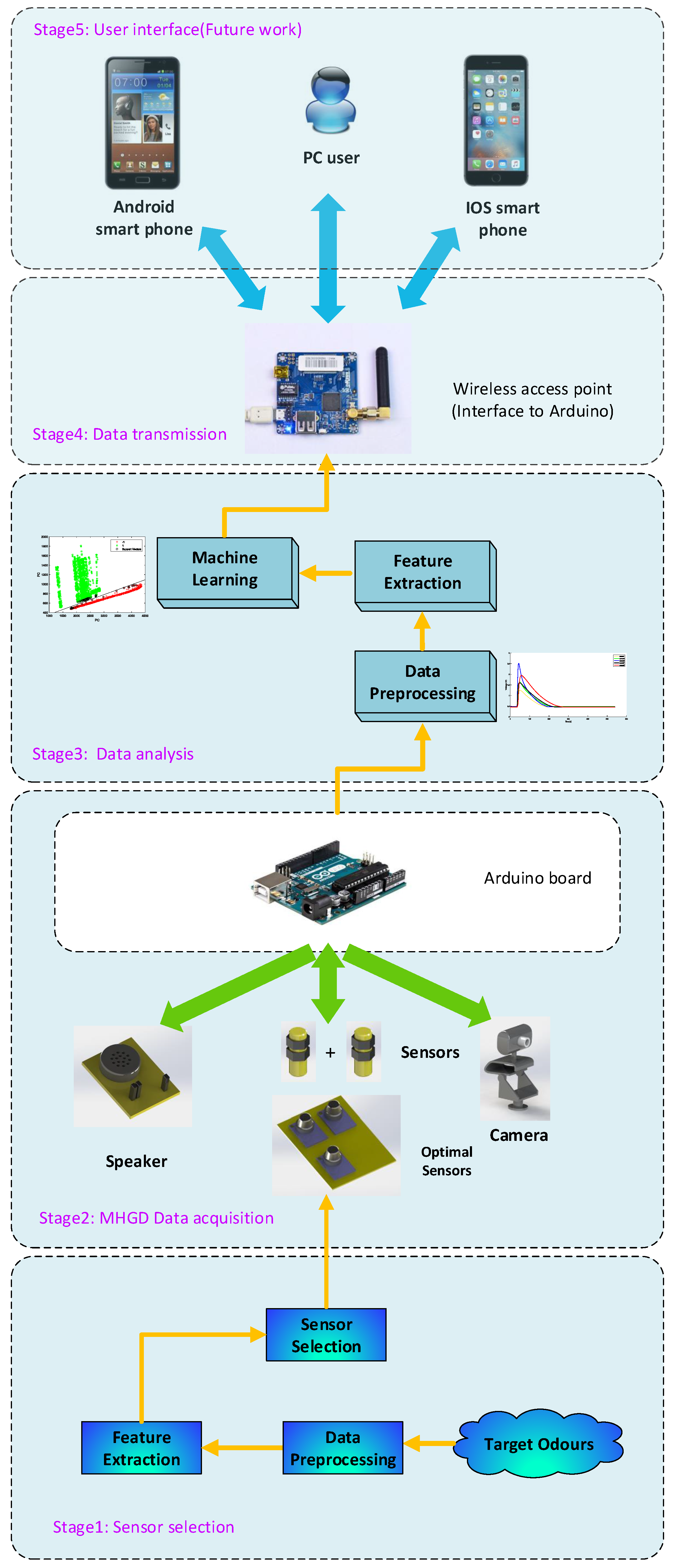
We will create an IoT-based Smart Electricity Energy Meter using ESP32 and the updated Blynk 2.0 application. By using the best current sensor (SCT-013) and voltage sensor (ZMPT101B), we can measure voltage, current, power, and total energy consumed in kWh. The readings will be sent to the Blynk 2.0 application and displayed on a dashboard An IoT (Internet of Things) based smart energy monitoring system allows you to track energy usage at your home or office in real-time. The system collects the data in logs and displays it in a meaningful manner that you can further use to perform actions, such as sound an alert or send notifications on your smartphone or Alexa/Google Assistant for high power usage or when energy usage reaches
DIY Smart Energy Meter With ESP32 + Home Assistant Circuit Diagram
You can create your own smart energy meter. You just need a Raspberry Pi and some open-source software. It'll cost way less than the smart meters sold by utility companies. The key components for creating a DIY smart energy meter are a Raspberry Pi, current transformers (CTs), a power supply, and a display. You'll also need usual

Basic electronics. (We are going to be using some electronics principles that are good to know to understand how this meter works). Handling of cutting tools and drills. How to solder. (To place the components we need). How to use a meter intruments as multimeters and clamp meters.

How to Make a Smart Energy Meter Circuit Diagram
The proposed system gives the information about the energy consumption on real time on IoT dashboard on mobile application and PC, billing through IoT, this smart energy meter protects your home from bad supply, alert the consumer and utility when the energy consumption exceeds above the set limit and the disconnection and reconnection of power
