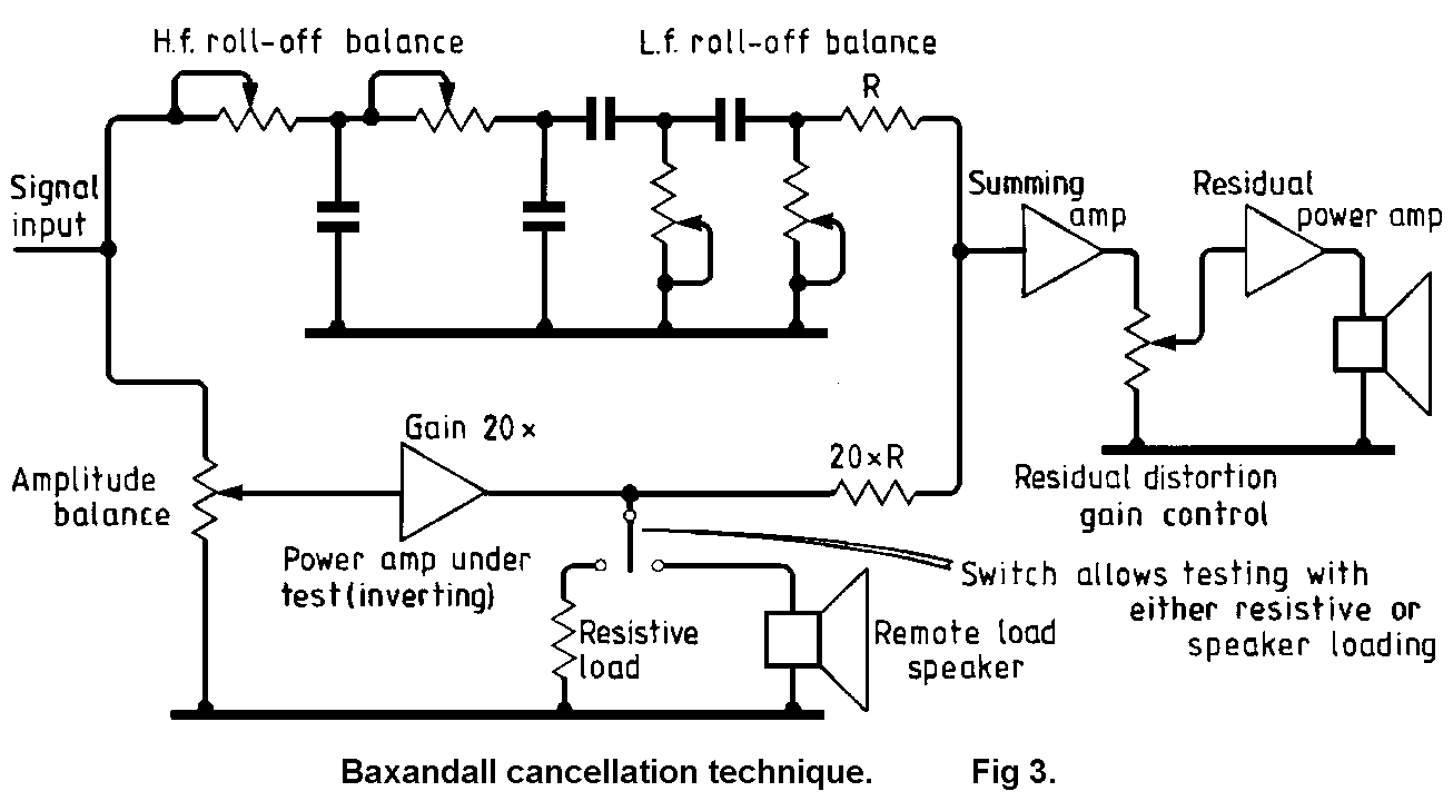
Musings on amp design a thread split Circuit Diagram
Musings on amp design a thread split Circuit Diagram The timing differences cause a constantly changing phase-shift between the original signal and the duplicated signal(s). notches are formed at the frequencies where the all-pass circuits created phase-shifts. Phaser parameters in Nectar Pro While there are lots of unique-sounding audio effects for sound design, there are a few you're

A phase shifter circuit is an electronic circuit that is used to shift the phase of a signal without changing its amplitude. It is a fundamental component in many signal processing systems and is used in applications such as audio processing, frequency synthesis, and phase modulation, AM modulation and demodulation, SSB modulation. There are several ways to build a phase shifter circuit, but Try this Active Phase Shift Circuit Calculator to simplify your design process. Step-by-Step Guide to Build the Circuit. Assemble Components: Gather all the materials listed. Breadboard Setup: Connect the components as per the circuit diagram. Testing and Tuning: Use a signal generator and oscilloscope to observe and fine-tune the phase shift.

Phase shifter circuit Working Principle Circuit Diagram
The overall phase shift is close to 360° across the audio band for circuit #1 (+180° at 20Hz and -180° at 20kHz). This is not audible. Circuit #2 has an overall phase shift of about 660° across the audio band, but this too is inaudible. See below for more info on the phase shift networks.

The Phase Shift Circuit Does This: Signal Source Input Output Three stage Phase Shift Network Note that each C-R section shifts the phase of the signal by 60 degrees. Thus the output is shifted by a total of 180 degrees with respect to the input. The frequency is 1050 Hz C20 = C21 = C22 = 0.022uF R20 = R21 = R22 = 3k Ohm

Understanding Chorus, Flangers, and Phasers in Audio Production Circuit Diagram
INTRODUCTION: „For great sounding multi-way driver relative phase must be equal at all frequencies. Period." Typical approach in loudspeaker design is provided in many articles as follows: choose drivers, choose baffle, choose crossover point and filter orders, apply corrections. Phase is too difficult to understand, so lets omit that.
